| Sep 10, 2012 | Severity: Recommended | Eugeny Brychkov (RU) |
This DN0003 design note is applicable to the storage subsystem microcode version 3.0 and above.
This DN0003
design note is licensed to GR8BIT Engineering Community, and put into public access as an evaluation of the quality of
product and related documentation and support services for potential customers.
Special thanks to Raymond van der Meulen (testing), Dominique Chuderski (testing), Jan Wilmans (DOS2 ROMs) and Albert Beevendorp (volume serial numbers) for help and support during development and testing of the GR8BIT storage subsystem.
Purpose of this document: This document is intended to provide to GR8BIT Engineering Community members, as well as other interested users and hardware, software and firmware developers who want to use GR8BIT storage subsystem v.3.0 and above, and use its API to connect and operate their own devices.
Overview of features: GR8BIT Storage subsystem version 3.0 supports the following configurations:
Storage subsystem now has built-in GR8STORM™ (GR8BIT storage manager) utility for subsystem configuration and hard disk preparation for use/recovery. Standalone GR8HDD.COM utility was discontinued.
Note: all references to FAT16 partitions assume usage of GR8BIT storage subsystem in MSX-DOS 2.20 mode. FAT16 partitions are not available for read/write in MSX-DOS 1.0 mode.
Compatibility considerations: There're several efforts made in order to maintain compatibility with MSX standard as well as to support MS-DOS/Windows (hereinafter referred as PC systems) formats:
Supported storage media configurations:
Limitations of functionality: Some functionality which may be desired is still missing (partially due to scarce disk driver ROM space):
In order to get storage subsystem version 3.0 up and running, please perform the following steps:
We recommend partitioning first (master) hard disk in the following way:
The rationale for such recommendation is to have LVOL0 with minimal number of FAT sectors with DOS1-supported OS to save high memory space when you boot into DOS1 mode, but at the same time have fully functional and bootable LVOL located on the hard disk. At any time you can use GR8STORM to deactivate LVOL0, and have LVOL1 of 32Mbytes of size appear in the GR8BIT drive map as first logical device located on the hard disk.
B Built-in means that you do not need any additional software or hardware in order to get declared functionality Boot sector is the 512-byte chunk of data and code at the beginning of logical area of the media. It contains vital information like media configuration, and boot loader. Floppy disk can have only one logical area (at logical sector 0, or CHS=0/0/1), hard drive may have several logical areas (partitions), and each partition is addressed relatively to the start of the hard disk having boot sector at its beginning
C Compatible format is a format of floppy disk with 3 sectors per FAT copy and having usable space of 1.44Mbytes. Floppy disks having compatible format can be read/written by GR8BIT and PC. Format is called "Compatible" because it is accepted by GR8BIT storage subsystem in compatible mode, and such disk's FAT copy in memory in DOS1 mode consumes only 1536 bytes. It differs with Legacy format in the total disk usable space size Compatible mode is the state of the storage subsystem when it can accept only floppy disks in Compatible and Legacy formats Cylinder/Head/Sector (CHS) is the method of addressing floppy and hard disk media. Contemporary floppy media are divided into circular cylinders (or tracks), and may have one of two heads. Each head can read track it is positioned on. Each track is divided into sectors (small arcs of the circular track). This method may be considered as obsolete for hard disk drives, however GR8BIT storage subsystem uses it to access disk hardware to support older drive models
D Driver is a program which runs either in RAM or ROM and acts as an interface between hardware and application software. It translates high level commands of application software to the low level commands recognizable by hardware Drive letter is an storage subsystem's identifier for storage device, e.g. A:, B: , C: DOS1 is a first generation of the kernels. Its maximal size, together with driver, is 16Kbytes, it has limited memory management (no use of mapper) keeping all its data structures in the high memory area DOS2 is a second generation of the kernels. Its maximal size, together with driver, is 64Kbytes, and it uses mini-mapper to switch between 16Kbyte pages. It has support for memory mapper management, and stores most its data into the upper pages of the RAM
F File allocation table (FAT) is a structure which allows storage subsystem to find data written for specific file on the media. Floppy disks and LVOLs usually keep 2 FAT copies to be able to restore data in case of one copy get damaged. If FAT becomes invalid, part of the data, or whole data read from the disk, becomes invalid, and restoration may require expert knowledge or tools Floppy disk controller (FDC) is an entity (chip or emulating device) which controls floppy disk drive(s) and decides which information is written on the diskette and at which location. It usually connects to the FDD using 34-wire ribbon cable Floppy disk drive (FDD) is a device where you insert floppy disks. This device is responsible for reading and writing media, and detecting its presence
K Kernel is a core of the storage subsystem BIOS (basic I/O system), which serves as intermediary between application software and custom hardware drivers. While drivers are responsible for ensuring information storage and access to hardware, kernel is responsible for keeping data stored in the structured format so that it can be easily restored if needed
L Legacy format is a format of floppy disk with 3 sectors per FAT copy and having usable space of 720Kbytes. Such format of disks is historically used in MSX-compatible computers having WD1793-compatible FDC Logical block addressing (LBA) is a method of addressing of contiguous space of the media or volume, with logical block 0 being located at the beginning of media, and block 1 following logical block 0 and so on Logical drive is a user-interface device usually addressed by the drive letter Logical volume is a contiguous area on the media (usually hard disk or disk array), which can be addressed by LBA method
M MSX-DOS is an operating system for MSX compatible computers. It is very similar to MS-DOS, but tailored for MSX computers. Master boot record (MBR) is the first sector (sector 0 in LBA terms) of the hard disk, which contains information about LVOLs (partitions) created on the hard disk. In GR8BIT it does not contain boot code, but contains LVOL recovery information. MBR is not directly accessible by the GR8BIT's CPU
S Standard format is a format using a maximal configuration for floppy disk. If you format floppy disk on PC, it will by default receive Standard format of 1.44Mbytes in size and 9 sectors per FAT copy. This format is compatible with PC Standard mode is the state of the storage subsystem when it can accept floppy disks in all the formats: Standard, Compatible and Legacy
Here're quick facts which may help you understanding how system behaves, and why it behaves in certain way. Understanding of the matters will allow you to perform initial troubleshooting and investigation.
You can configure GR8BIT storage subsystem in smart ways which fit your immediate requirements. The configuration information is stored within microcontroller's EEPROM and is kept when you switch off the system.
Configuration is performed using built-in GR8STORM™ utility. During any prompt for your input you may press CTRL-C or CRTL-BREAK keys to cancel the operation, get out to the higher level menu, or exit the utility. Please note that after specific changes to the configuration of LVOLs you are prompted to reboot the system. Structure of GR8STORM's menus is presented in table 5.1.
Table 5.1. Structure of GR8STORM's menus
| Main menu | Submenus |
|---|---|
| 1. Operation mode | Floppy subsystem |
| HDD subsystem | |
| Device order | |
| FDD mode | |
| Phantom floppy | |
| Write to EEPROM | |
| 2. Boot message | Clear message |
| Set new message | |
| 3. Media configuration | Reset and enumerate hardware |
| Update floppy boot sector to DOS2 | |
| Partition hard disk | |
| Change partition activation status | |
| Initialize/recover Logical Volume (LVOL) | |
| 4. Diagnostic outputs | Display MC's workset |
| Display MC's buffer contents | |
| Display FDD0's floppy disk's boot sector | |
| Display HDD0's MBR and LVOLs' boot sectors | |
| Display HDD1's MBR and LVOLs' boot sectors |
Operation mode defines the way how storage subsystem functions. It has several settings, which can be combined together to create a set of handy configurations for various applications.
Examples of applications: operating GR8BIT in DOS1 mode and lacking of user memory, you can disable phantom floppy. To boot from LVOL in DOS1 mode prioritize HDD first, and then drive A: will appear to be first LVOL configured. Disable floppy subsystem if you do not use it.
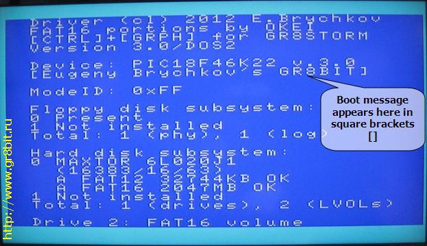
You may have message of maximum 24 characters displayed at the boot of the GR8BIT during initialization of the storage subsystem (fig. 5.1). This message is stored in microcontroller's EEPROM, and is not lost when you power system off. We advise not to put any text there for which you would feel uncomfortable or judged inappropriately.
This section of GR8STORM allows you to re-initialize storage subsystem, update floppy boot sector and configure hard disks for use.
If you have issues with storage subsystem, or want to view control data of the microcontroller and storage devices, you will use diagnostic outputs for troubleshooting.
There're several very useful shortcuts available at the beginning and at the end of the GR8BIT storage subsystem initialization. Please refer to the table 5.2 for details. Remember that you should allow GR8BIT PS/2 keyboard controller to initialize within 4 seconds after system power on, not pressing any keys during this period of time.
Table 5.2. Keyboard shortcuts
| Key (keys) | Description |
|---|---|
 | Disk-ROM will not install. Works in DOS1 mode only |
 | Forces storage subsystem to initialize in DOS1 mode. FAT16 volumes are not available. Devices' structures (DPBs and buffers) are located in the upper memory |
 | Cancels installation of the FAT16 patch. Works in DOS2 mode only |
 | Disables floppy disk subsystem |
 | Disables hard disk subsystem |
 | Forces storage subsystem to configure in Compatible mode |
  |
Starts GR8STORM™ built-in utility. This key combination is sampled at the end of the subsystem initialization |
Answer to this question is very important because CPU visible memory is limited even with GR8BIT having mapped 1MB of main SRAM. Ability to run programs and games is dependent on how much memory is available, and where system-s control structures are located in the memory.
If you have no storage subsystem installed or configured in the system (e.g. if you are in DOS1 and no media was detected), then you will have about 28.8 Kbytes free memory.
If you start system in DOS2 mode (not necessarily boot into the MSXDOS), DOS2 kernel will have advanced memory mapping capabilities, and disk buffers, control structures and other stuff will be located in the last pages of the mapper RAM. It will not consume much of valuable space in the high visible memory space (in bank 3, from 0C000h...0FFFFh), and you always will have 25 Kbytes user space free in BASIC and 57 Kbytes free with operating system loaded, regardless of number of logical drives and their sizes. However such an advanced configuration may not be supported by earlier software designed for DOS1 with no memory management, software performing its own memory management. Such software may not work properly in DOS2 environment.
If you start system in DOS1 mode (by booting from DOS1-type floppy disk or holding Backspace key on storage subsystem initialization), you will get DOS1 kernel with no memory management, and information about drives and buffers will be allocated in the memory bank 3 and user available memory will be automatically reduced by the amount allocated. Consider configurations described in table 5.3.
Table 5.3. Examples of FDD configurations and memory available
| Configuration | Bytes used |
|---|---|
| 1 FDD Phantom = disabled Compatible mode | In Compatible mode space for 3 FAT sectors per logical drive is allocated, and you will get 1536 bytes (512*3) less free space |
| 2 FDDs Phantom = n/a Compatible mode | 1536 bytes are allocated twice, for every floppy drive's logical device, so minus 3072 bytes |
| 1 FDD Phantom = enabled Compatible mode | Phantom drive is a second logical floppy drive using the same physical floppy drive. Two logical drives = minus 3072 bytes |
| 2 FDDs Phantom = n/a Standard mode | In Standard mode space for 9 FAT sectors per logical drive is allocated (4608 bytes). With 2 logical drives in Standard mode you will get 9216 bytes user free space less |
For every LVOL configured system will allocate space equal to 512 bytes multiplies by the number of sectors in file allocation table (FAT). See table 5.4.
Table 5.4. Examples of LVOL configurations and memory available
| Configuration | Bytes used |
|---|---|
| FAT16 volume | Whatever number of FAT sectors it has, it will be allocated dummy number of sectors equal to 3, and will cause minus 1536 bytes. FAT16 volumes are not supported by DOS1 kernel |
| FAT12 volume 3 sectors | 3 sectors by 512 bytes = 1536 bytes less |
| FAT12 volume 12 sectors per FAT | 12 sectors by 512 bytes = 6144 bytes less |
Before GR8BIT will get to operating system (OS) load procedure, or to the BASIC if OS in not present on the first media system finds, disk ROM will perform initialization of the storage subsystem and enumeration of the logical volumes (LVOLs) located on the hard disk drives.
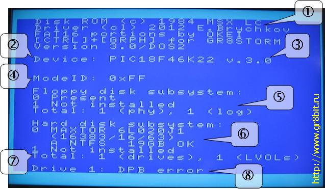
Figure 5.2 shows messages of the GR8BIT storage subsystem initialization screen. Let's consider every part, as each provides you with important information:
| Bit # | Function |
|---|---|
| 7 | 0 = Disable Hard disk drive subsystem |
| 6 | 0 = Disable Floppy disk drive subsystem |
| 2 | 1 = floppy drive devices go first |
| 1 | 1 = Phantom floppy disk device is disabled |
| 0 | 1 = Floppy disk drive subsystem is in Compatible mode |
In the DOS1 mode subsystem will only attempt to boot from first drive configured in the system drive A:. If you have floppy disk system configured first, it will boot from floppy drive 0, if hard disk system first, then from first LVOL is configured from hard disk 0.
In DOS2 mode GR8BIT will try every storage device available (max 8) to see if it can boot from it, thus if you have configured floppies first, with single floppy and phantom drive disabled, it will first try booting from floppy drive (A:), and if unsuccessful will boot from first LVOL (B:).
The following prerequisite should be met to boot to the MSX-DOS operating system from the specific device:
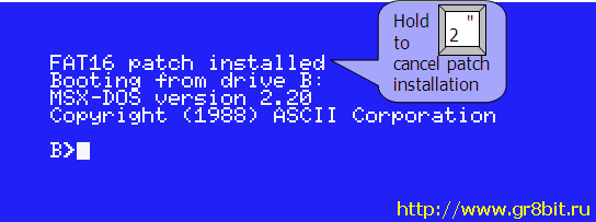
When GR8BIT starts booting, it automatically applies FAT16 patch by OKEI (fig. 5.3). If, for some reason, you do not want FAT16 patch to be applied, hold "2" key at the start of the boot process.
If storage subsystem detects no floppy drives, first LVOL becomes drive 0 (A:) and can be booted from even in DOS1 mode. Note that DOS1 kernel requires at least one logical drive to be configured. If you detach all storage devices from controller, or disable floppy and hard disk subsystems via operation mode menu, system will not install DOS1 kernel at all.
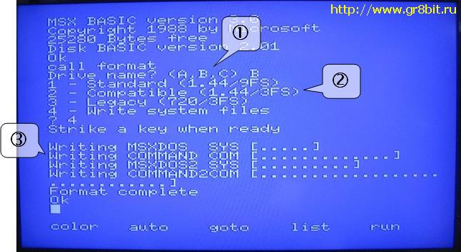
Important feature of the GR8BIT storage subsystem version 3.0 is that it has original versions of MSX-DOS and MSX-DOS2 flashed into its microcontroller. You may have MSX-DOS operating system without having any media containing required files. Use FORMAT built-in utility from either MSX-BASIC or from MSX-DOS. Important: FORMAT utility was relocated to the end of the page 2 of the DOS2 storage ROM, and will work with built-in FAT16 patch installed. However if you will run external FAT16.COM application with /R key (uninstall) and then install it back, FORMAT utility will stop working until you remove FAT16 patch using this external FAT16.COM application. It happens because FAT16.COM disables FORMAT utility (it does not know that GR8BIT storage subsystem has FORMAT utility code relocated to the safe place in its ROM).
There's nothing about configuration of the floppy drives other than just attaching them to the respective connector on the floppy cable. Ensure that you use regular FDDs you used to use with your PC with DC (disk change) option (pre-) set. Disk drives which are configured with RDY option will not work.
Configuring diskettes involves formatting them - laying out sector information in the raw media space, and filling these sectors with proper information (boot sector, FAT, directory).
There're two options for formatting diskettes:
If you have formatted floppy disk on the PC, please use GR8STORM™ Update floppy boot sector to DOS2 submenu instead of FIXDISK.COM to make it bootable by the GR8BIT (FIXDISK will return Invalid MSX-DOS call).
You will use GR8STORM built-in utility to partition the hard disk, initialize or recover volume structure on its LVOLs. The utility works in 80-column screen mode in order to provide the best layout of the information on the screen.
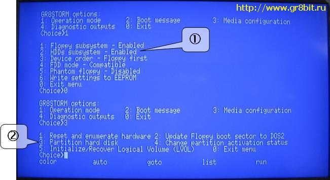
Invoke GR8STORM using "call gr8storm" BASIC command or holding CTRL+GRAPH during storage subsystem initialization. Fig. 5.5 shows start of the dialogue; first ensure that hard disk subsystem is enabled (1) and then follow to the "Partition hard disk" menu (2).
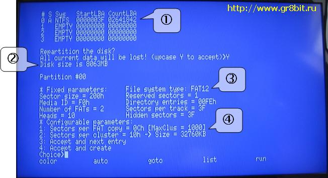
You select hard disk drive number, and have its partition listed (1 at fig. 5.6). Then you confirm that you want to proceed further, and get into the partition configuration menu. You see disk size listed (2), and note that it is maximal supported size in CHS mode and not actual hard disk drive size which can be larger. First partition will always be FAT12 (3).
There're only two tunable options:
After the calculation the LVOL you are going to create will have the size equal to Clusters * 2SpC * 512 bytes and maximal value for FAT12 volumes equals to 4096 * 24 * 512 = 32Mbytes, and for FAT16 volumes equals 65536 * 26 * 512 = 2Gbytes. You will see this calculated value in the "Size =" section.
You can play with the settings to create different sizes of the volumes, and create multiple, up to 4 volumes choosing menu option "Accept and next entry". LVOLs 1, 2 and 3 created on the hard disk may be either of FAT12 or FAT16 type.
When you filled up all 4 entries or chosen "Accept and create", you are again asked for prompt if you really want to proceed. If you choose uppercase "Y", it will rewrite all the control structures on the disk and previous structures will be lost.
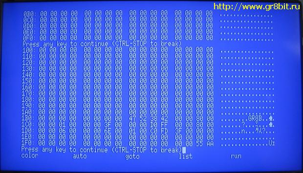
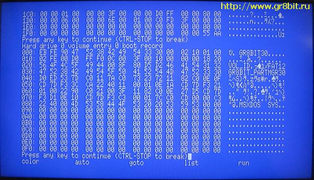
LVOLs need not to be "formatted" after you finish their configuration with GR8STORM. You can view the structures tool has created for you by going to Diagnostic outputs menu and choosing option 4 Display HDD0's MBR and LVOLs' boot sectors (fig. 5.7 and 5.8).
After reboot you may copy system files and application to the newly configured LVOL, and use it as any regular storage device addressing it by the respective drive letter.
Limitations: GR8STORM (a) only writes LBAs into the MBR LVOL configuration, and does not write corresponding C/H/S values of start and end of partition; (b) it does not write PC bootstrap code into MBR (PC will not be able to boot from this hard drive), however hard drive is expected to be readable if attached to the PC's IDE controller.
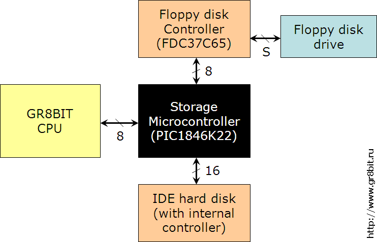
Subsystem is based on several components (fig. 6.1), which provide specific API for developers to extend its functionality. Microcontroller with multi-stage architecture was introduced in order to have reliable access to the media, and have unified entry point to any attached storage device. Without MC GR8BIT, and any other MSX-compatible computer, is unable to reliably control floppy disk controller data flow at 500KBit/s speed due to insufficient CPU speed at 3.58MHz system clock.
If you want microcontroller to have more functionality for floppy disk controller, you develop modifications and add-ons to the microcontroller microcode. As an example, it is not really required to have IDE disk drive connected to the 40-pin connector - you may design and build adapter to connect any device and alter microcontroller functionality appropriately.
If you want to change API between GR8BIT CPU and microcontroller, you will need first have this API defined from MC side, and then implement CPU-side routines modifying GR8BIT storage ROM.
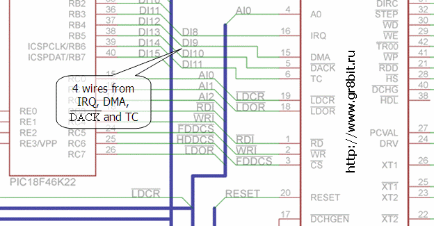
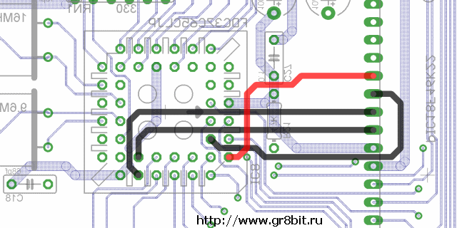
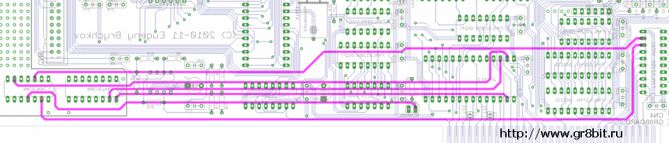
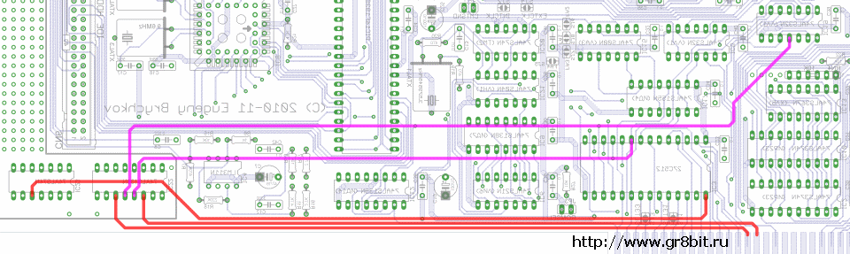
Floppy disk controller was initially designed to work in PIO mode; unfortunately all the attempts to make it work reliable in PIO mode did not succeed. We decided to implement DMA transfers, and this way of interfacing succeeded. In order for your GR8BIT storage hardware to support DMA floppy disk controller interface and current release of microcode, you will need to add 4 (four) air-wires connecting IRQ, DMA, DACK and TC pins of FDC to the specified pins of port B of MC (fig. 6.2 and 6.3).
Unlike initially chosen PIC16F1939, new microcontroller PIC18F46K22 (which is a direct replacement for former) is twice faster and is able to serve GR8BIT CPU requests without additional wait stated introduced by slowdown circuit.
PIC18F46K22 has 3896 bytes of SRAM, and it can read up to 7 sectors per one DSKIO API call. After the read operation, MC returns number of sectors actually read for GR8BIT CPU to read valid user data from the MC's data buffer. Such a technique, coupled with DMA access method, dramatically increased floppy disk transfers speed relative to previous implementations.
IDE interface uses PIO transfers Mode 0 only and CHS media access method to maintain compatibility with older ATA/IDE hard disk drives. If you wish you can change timing of the IDE bus modifying MC's related microcode to speed up HDD data I/O port access.
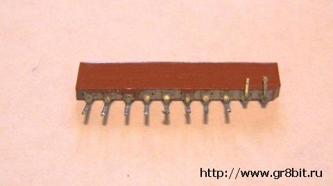
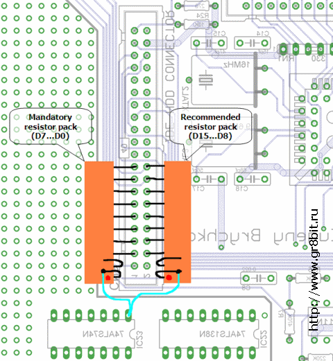
Unfortunately initial electrical design of the IDE interface has non-critical flaw: it should have pull-up resistors on its data lines. The symptoms can only be experienced if no HDD is connected - due to no pull-up resistors and no active-output device on the bus, storage microcontroller does not read valid value (either 00h or 0FFh), and thinks there's something attached to the IDE interface. This flaw can be easily fixed by adding at least one resistor pack, 10KOhms in nominal resistance.
We recommend following the following steps:
In default design GR8BIT allows its CPU to "see" storage subsystem ROM's content in the banks 1 (4000-7FFF) and 2 (8000-BFFF), first half of the 64Kbyte IC3 chip if jumper JP3 is closed, and second half if it is open. The 16Kbyte pages within 32Kbyte visible space appear exchanged, i.e. if you have JP3 open, then system will see chip's contents in the range C000-FFFF in the page 1 (addresses 4000-7FFF) and contents in the range 8000-BFFF in page 2 (addresses 8000-BFFF). This way, if you do not implement DOS2 mini-mapper, you may have DOS1 ROM image (which is located in the ROM chip in space C000-FFFF) visible to the CPU at addresses 4000-7FFF and allow it to function properly in DOS1 mode.
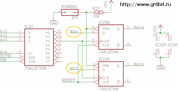
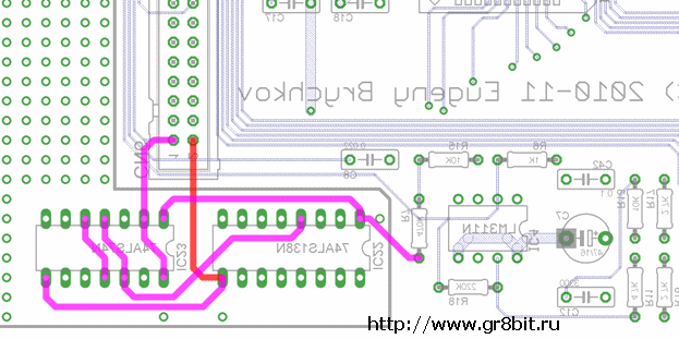
Figure 6.6 shows circuit diagram of the DOS2 mini-mapper. You will add two chips, and cut three tracks on the board. If JP3 is closed, both IC23 trigger Q outputs are set to logical 1, and IC3's A14 and A15 lines are steadily set to 11 (page 3), causing GR8BIT to always see DOS1 ROM image. If JP3 is open, triggers' outputs after system reset is 00 (page 0) GR8BIT can switch between banks writing to the address range 6000-6FFF when storage ROM is visible in the CPU space. Page change is performed when the following conditions are met at the inputs of IC22 (fig. 6.6): A15=A12=0, A14=A13=0 (address space 6xxxh), WR signal is active (system is writing to the memory or port), and SLTSL is active (CPU address points to the sub-slot space identified by the respective SLTSL signal - SJ1 or SJ3 jumpers of the I/O board).
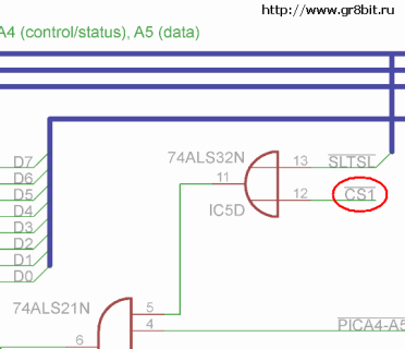
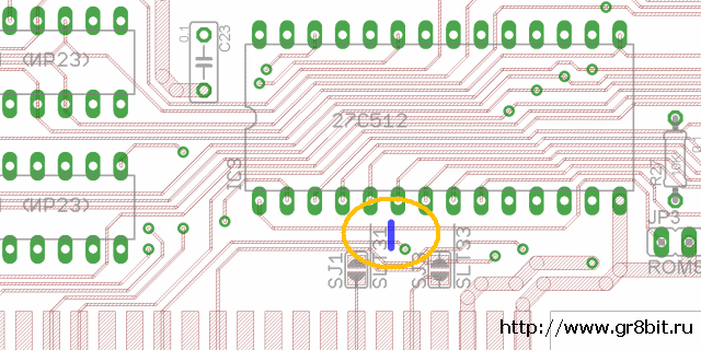
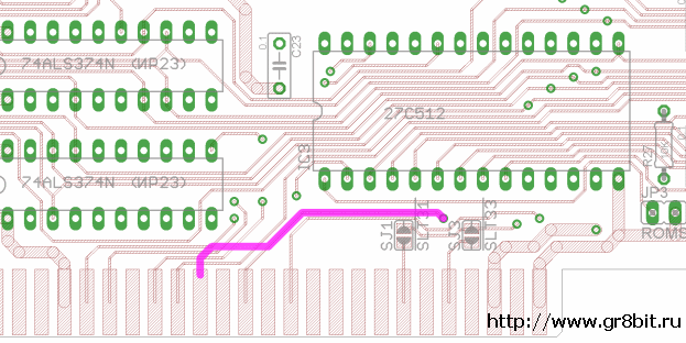
ROM chip select signal need also be changed from CS12 to CS1 (fig 6.7) so that storage ROM pages would appear only in the bank 1 (addresses 4000-7FFF). If we would leave CS12 signal, then CPU may erroneously find something "useful" in the bank 2 and try working with it - and such a condition may yield unexpected results and affect system stability.
It is important to wire data input lines of the IC23 trigger elements directly to the GR8BUS data lines (BDx), not to the I/O board buffered data lines. I/O board's data buffer IC1 is activated only for EPROM read using CS1 and SLTSL signals (IC5D), but CS1 signal only activates on read from the bank 1 (see IC31B on the main board's schematic - it uses RD signal to activate de-multiplexer element).
 (a) |
 (b) | |
| Figure 6.7. Modifications to the "chip select" line - from CS12 to CS1 | ||
Here's the list of steps to implement changes in order to have DOS2 mini-mapper in your GR8BIT system.

 (a) |
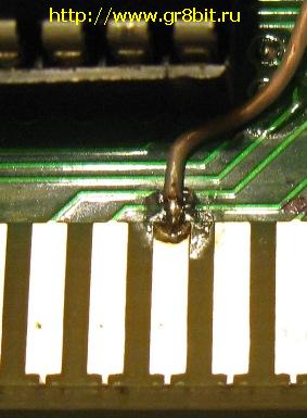 (b) | |
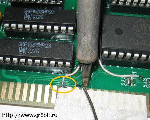
| Figure 6.9. Tinning edge connector's pad (a), and having air-wire connected (b) Note: CS1 signal is circled orange on the picture to the left. In this example we tin another pad as CS1 was already tinned before. | ||

Application API is used by the GR8BIT and other compatible application programs to access resources attached to the GR8BIT storage subsystem; they will use standard system (BASIC or MSX-DOS) calls. Disk subsystem calls (such as INIHRD, DSKIO, DRIVES, DSKCHG, GETDPB) are not expected to be used by application software (are used by system software).
The minor, but important change was introduced to the DSKIO system call to support 23-bit sector numbers: if bit 7 of register C (media descriptor) is reset, then remaining 7 bits are treated as upper sector number. With such a mechanism system and application software can address volumes with up to 8,388,608 sectors (4Gbytes). In terms of DSKIO system call, this 23-bit sector address is a sector offset relative to the base of the LVOL, which is always 32-bit. Hard disks' MBR is not directly addressable by application or system calls because MBR is located out of LVOL addressable space.
GR8BIT will flash alternate screen color if application or system software tries to load data onto the stack memory location, with DSKIO returning Write Protected error for read operation. This functionality is very useful in DOS1 mode in multiple disk drive configurations when significant portion of memory is used by the disk buffers and programs may not fit into available free memory.
System API is used by the GR8BIT storage subsystem ROM and system utilities to control storage microcontroller (MC). Following is the list of the commands available for the system software (table 7.1). Detailed explanation of the API and CPU-microcontroller data exchange is provided in the next section.
Table 7.1. List of the available MC commands
| Cmd | Name | Purpose |
|---|---|---|
| 00 | INIHRD | Initialize storage system. Enumerates physical floppy drives, recalibrates them and populates LVOL structures in its workset. Returns number of logical devices configured (use by DOS1 ROM to cancel installation of the storage ROM) |
| 01 | DSKIO-R | Read of a set of sectors to the MC buffer, maximal number of sectors per call: 7 (limited by the size of internal MC's SRAM). Logical sector access (23-bit). Returns number of sectors actually read |
| 02 | DSKIO-W | Write a set of sectors from the MC buffer, maximal number of sectors per call: 7 (limited by the size of internal MC's SRAM). Logical sector access (23-bit). Returns number of sectors actually written |
| 03 | DSKCHG | Get floppy drive's disk change status |
| 04 | FMTDSK | Format floppy disk |
| 05 | DRIVES | Get number of logical devices served by storage subsystem |
| 06 | VERSION | Get MC's identification string |
| 07 | SOFTWARE | Get a chunk of the system software (MSXDOS.SYS, MSXDOS2.SYS, COMMAND.COM, COMMAND2.SYS) |
| 08 | GR8STORM | Perform user dialogue with GR8BIT storage management utility |
| 09 | HDDSTAT | Get contents of the specified HDD unit's status and error register |
| 0D | INIDPB | Is used by the GR8BIT storage ROM to get drive parameter block (DPB) information about the logical device |
| 0E | PROMPT | Check if floppy drive host is about to access has actual diskette according to the phantom logical drive, and return flag is host should prompt to insert actual diskette |
| 0F | GETDPB | Get DPB of the media in the specified logical device. DPBs of LVOLs are considered always intact |
| 10 | HDDID | Get HDD identification information (Identify command). Full 512 bytes of identification information are returned |
| 11 | BUFACC-R | Read from MC buffer |
| 12 | BUFACC-W | Write to MC buffer |
| AA | ECHO | Tests whenever MC is present and/or available within the system |
In the following section Port 0 is I/O port at address 0xA4, and Port 1 is I/O port at address 0xA5. The following operations read or write to these ports:
| Port 0 | Port 1 | |
|---|---|---|
| Read | DB A4: IN A,(0A4h) | DB A5: IN A,(0A5h) |
| Write | D3 A4: OUT (0A4h),A | D3 A5: OUT (0A5h),A |
This command is used to test if MC is ready to accept commands. CPU sends 0xAA to the MC, and MC replies 0xAA. Next byte read after 0xAA should be 0xFF.
| Type | Description | Byte | Port | Host R/W |
|---|---|---|---|---|
| Command | ECHO Check MC ready | 0xAA | Port 0 | W |
| (microcontroller) | Response | 0xAA | Port 1 | R |
INIHRD initializes storage subsystem (floppy disk and hard disk - according to configuration set in EEPROM) and its variables.
| Type | Description | Byte | Port | Host R/W |
|---|---|---|---|---|
| Command | INIHRD Initialize storage subsystem | 0x00 | Port 0 | W |
| (floppy) | Command accept flag | 0xAB | Port 1 | R |
| Confirmation code | 0xEC | Port 1 | W | |
| Perform dialogue with the GR8BIT CPU | ||||
| Read number of logical devices configured | 0x01 | Port 1 | R | |
These commands read or write logical sector. DSKIO allows programmer to address logical devices (not physical ones). Maximal number of contiguous sectors MC can read or write is 7 (512 bytes * 7 = 3584 bytes). Reads or writes are performed to/from MC's buffer, thus programmer should successfully load valid data using BUFACC-W command before writing, and get valid data from the buffer using BUFACC-R command after reading. C/H/S values for floppy drives and hard disks are calculated by the MC basing on the values of sector per track and heads obtained by the MC from respective device's boot sector.
| Type | Description | Byte | Port | Host R/W |
|---|---|---|---|---|
| Command | DSKIO Sector read (write) with retries | 0x01 (0x02) | Port 0 | W |
| Command accept flag | 0xAB | Port 1 | R | |
| Logical device identifier 0=drive A: | 0x01 (B:) | Port 1 | W | |
| Number of sectors to process | 0x07 (maximum) | Port 1 | W | |
| Media ID/Sector # bits 22..16 * ** | 0xF9 (descriptor) | Port 1 | W | |
| Sector # byte 0 ** | 0x00 | Port 1 | W | |
| Sector # byte 1 ** | 0x00 | Port 1 | W | |
| Command execution phase (read or write), filling MC buffer | ||||
| Refult flag | 0xAF | Port 1 | R | |
| Number of sectors successfully processed | 0x01 (remaining 6 were not) | Port 1 | R | |
| Completion status read | See table 7.2 | Port 1 | R | |
This command reads status of the floppy disk change line off the specified logical device. It returns 0xFF is media was changed since last call, or 0x01 if media was not changed. Calling DSKCHG resets disk change flag. For hard disk-based LVOLs DSKCHG command always returns 0x01 (not changed).
| Type | Description | Byte | Port | Host R/W |
|---|---|---|---|---|
| Command | DSKCHG Check device's change status | 0x03 | Port 0 | W |
| (floppy) | Command accept flag | 0xAB | Port 1 | R |
| Device# 0=drive A: | 0x01 (B:) | Port 1 | W | |
| Command execution phase | ||||
| Result phase flag | 0xAF | Port 1 | R | |
| Disk change status read | 0xFF (chg) 0x01 (n-chg) | Port 1 | R | |
DSKFMT command formats floppy disk. It does not partition or format HDD - please use GR8STORM™ built-in utility for these tasks.
| Type | Description | Byte | Port | Host R/W |
|---|---|---|---|---|
| Command | DSKFMT Format floppy media | 0x04 | Port 0 | W |
| (floppy) | Command accept flag | 0xAB | Port 1 | R |
| Device# 0=drive A: | 0x00 (A:) | Port 1 | W | |
| Format parameter | See table below | Port 1 | W | |
| Confirmation code | 0xEC | Port 1 | W | |
| Format command start flag | 0xAE | Port 1 | R | |
| Drive initialization, disk format, and boot/FAT/directory sectors initialization | ||||
| Result phase flag | 0xAF | Port 1 | R | |
| Completion status read | See table 7.2 | Port 1 | R | |
Format parameter definition
| Value | Description |
|---|---|
| 0 | Standard 1.44 (9 sectors per FAT copy, 18 sectors per track) |
| 1 | Compatible 1.44 (3 sectors per FAT copy, 18 sectors per track) |
| 2 | Legacy 720 (3 sectors per FAT copy, 9 sectors per track) |
Returns number of logical devices configured by the storage subsystem.
| Type | Description | Byte | Port | Host R/W |
|---|---|---|---|---|
| Command | DRIVES Get number of logical devices | 0x05 | Port 0 | W |
| (system) | Command accept flag | 0xAB | Port 1 | R |
| Number of logical devices | 0x01 (1 drive) | Port 1 | R |
This command returns MC's identification string, terminated with 0xFF. All the characters returned are ASCII ones, except terminating character.
| Type | Description | Byte | Port | Host R/W |
|---|---|---|---|---|
| Command | VERSION Get version of MC firmware | 0x06 | Port 0 | W |
| (microcontroller) | Command accept flag | 0xAB | Port 1 | R |
| MC firmware ID string (read in loop) | Terminated with 0xFF | Port 1 | R |
MC has 64Kbytes of the internal flash ROM, and it keeps copies of original MSXDOS.SYS (v1.03), COMMAND.COM (v.1.11), MSXDOS2.SYS and COMMAND2.COM (v2.20). Images of this software can be downloaded using SOFTWARE command in 512-byte chunks. By default these images are not designed to be bootable off the MC.
Chunk #0 contains package identification information: file name (11 bytes), 0x00 (initial extent #), size in bytes (2 bytes) and remaining fill bytes up to 512 byte chunk size. Maximal size of the package (memory space which can be addressed with chunk ID) is 26 * 512bytes = 32Kbytes. It is practically possible to read contents of MC's flash ROM beyond the last valid chunk of the package. Package image starts at chunk #1. Bytes within last chunk beyond package size are not invalid.
| Type | Description | Byte | Port | Host R/W |
|---|---|---|---|---|
| Command | SOFTWARE Get chunk of the system SW | 0x07 | Port 0 | W |
| (floppy) | Command accept flag | 0xAB | Port 1 | R |
| Package ID and chunk ID | See table below | Port 1 | W | |
| Data exchange is required flag | 0xAE | Port 1 | R | |
| Confirmation code | Data byte (512 times) | Port 1 | R | |
| Sending CRC for checking | 8-bit CRC | Port 1 | W | |
| Result phase flag | 0xAF | Port 1 | R | |
| Completion status read | 0xCC (success) 0x00 (CRC err) | Port 1 | R |
SOFTWARE command parameter format
| Bit | Description |
|---|---|
| 7..6 | 00 Return 512 byte chunk of data from image of MSXDOS.SYS 01 Return 512 byte chunk of data from image of MSXDOS2.SYS 10 Return 512 byte chunk of data from image of COMMAND.COM 11 Return 512 byte chunk of data from image of COMMAND2.COM |
| 5..0 | Data chunk number (in 512 byte increments, thus maximal size of the software package can be 32KBytes) |
This command invokes dialogue between GR8BIT CPU and microcontroller, with CPU (user) provides input to the GR8STORM application, and MC performing requested actions and giving results back to the CPU (user). Dialogue is text-based. Please review section 7.3 for description on how dialogue works.
| Type | Description | Byte | Port | Host R/W |
|---|---|---|---|---|
| Command | GR8STORM Invoke dialogue with built-in GR8BIT storage manager | 0x08 | Port 0 | W |
| Command accept flag | 0xAB | Port 1 | R | |
| Confirmation code | 0xEC | Port 1 | W | |
| Perform dialogue with the GR8BIT CPU | ||||
This command allows host to identify the status of the respective HDD. It supplies status register, identifying readiness of the drive, and error register, which contains relevant information in case of status register's bit 0 ERR is set.
| Type | Description | Byte | Port | Host R/W |
|---|---|---|---|---|
| Command | HDDSTAT Get HDD status information | 0x09 | Port 0 | W |
| (hard disk) | Command accept flag | 0xAB | Port 1 | R |
| HDD ID # | 0x01 (slave) | Port 1 | W | |
| HDD status register | Byte | Port 1 | R | |
| HDD error register | Byte | Port 1 | R |
This command is issued by the host's CPU to perform initial configuration of the drive parameter blocks (DPBs) of the logical devices. DPB data is obtained from boot sector, which is read from the device or volume associated with logical device number supplied. For FAT16-type LVOL command fails with completion status code 0xCD, which signals to host CPU to apply dummy DPB.
| Type | Description | Byte | Port | Host R/W |
|---|---|---|---|---|
| Command | INIDPB Initialize logical device's DPB | 0x0D | Port 0 | W |
| Command accept flag | 0xAB | Port 1 | R | |
| Logical device# 0=A: | 0x02 (C:) | Port 1 | W | |
| Read of media's boot sector and construction of the DPB | ||||
| Result phase flag | 0xAF | Port 1 | R | |
| Completion status read | See table below | Port 1 | R | |
| If result flag indicated success, return 12 bytes of DPB | (12 bytes) | Port 1 | R | |
INIDPB completion code description
| Value | Description |
|---|---|
| 0x00 | Fail, unable to construct DPB, no DPB data will be returned |
| 0xCC | Successful completion, DPB will be returned |
| 0xCF | Successful, but number of directory entries was truncated to 0xFE |
| 0xCD | Fail, media has FAT16 identifier, DOS1 DPB does not matter |
This command returns flag to the host CPU it should ask user to insert another diskette into the drive, and allows proper operation of the phantom floppy drive.
| Type | Description | Byte | Port | Host R/W |
|---|---|---|---|---|
| Command | PROMPT Get information if prompt required | 0x0E | Port 0 | W |
| Command accept flag | 0xAB | Port 1 | R | |
| Logical device# 0=A: | 0x00 (A:) | Port 1 | W | |
| Completion status read | See table below | Port 1 | R |
PROMPT completion code description
| Value | Description |
|---|---|
| 0x00 | Logical floppy drive requested is different than current one, prompt is required |
| 0xCC | No prompt is required |
| 0xCD | Logical device is LVOL, no prompt is required |
This command is issued by the host's CPU to get current up-to-date version of DPB. In case of success, constructed DPB is located at the offset 0x200 in the MC's buffer.
| Type | Description | Byte | Port | Host R/W |
|---|---|---|---|---|
| Command | GETDPB Get logical device's DPB | 0x0F | Port 0 | W |
| Command accept flag | 0xAB | Port 1 | R | |
| Logical device# 0=A: | 0x00 (A:) | Port 1 | W | |
| Read of media's boot sector and construction of the DPB | ||||
| Result phase flag | 0xAF | Port 1 | R | |
| Completion status read | See table below | Port 1 | R | |
| If result flag indicated success, return 12 bytes of DPB | (12 bytes) | Port 1 | R | |
GETDPB completion code description
| Value | Description |
|---|---|
| 0x0? | Fail, media error or timeout (code is the one returned by DSKIO) |
| 0xCC | Successful completion, DPB will be returned |
| 0xCD | Fail, media is LVOL, no DPB update is required |
This command reads HDD identification information (such as physical configuration and model string) into the MC's buffer at location 0x000. After successful completion of the command, buffer will contain 512 byte structure returned by the hard disk drive.
| Type | Description | Byte | Port | Host R/W |
|---|---|---|---|---|
| Command | HDDID Get hard disk drive ID information | 0x10 | Port 0 | W |
| (hard disk) | Command accept flag | 0xAB | Port 1 | R |
| HDD ID and data type to return | 0x00 (HDD0) | Port 1 | W | |
| Identification information is read into the buffer at 0x100 | ||||
| Result phase flag | 0xAF | Port 1 | R | |
| Completion status read | See table 4.2 | Port 1 | R | |
BUFACC command is used to access MC's internal buffer. Valid buffer starts at 0x000 and ends at 0xDFF (3584 bytes), but practically programmer can read and write above this space, altering or damaging MC's operations. In the example in the table below host reads (0x11) 18 bytes from MC buffer location 0x200 (e.g. DPB image after successful DPB construction by GETDPB command).
| Type | Description | Byte | Port | Host R/W |
|---|---|---|---|---|
| Command | BUFACC Read from (write to) MC buffer | 0x11 (0x12) | Port 0 | W |
| Command accept flag | 0xAB | Port 1 | R | |
| Byte count, LOW | 0x12 | Port 1 | W | |
| Byte count, HIGH | 0x00 | Port 1 | W | |
| Buffer offset, LOW | 0x00 | Port 1 | W | |
| Buffer offset, HIGH | 0x02 | Port 1 | W | |
| Data ready flag | 0xAE | Port 1 | R | |
| Byte count | Read data bytes | Data bytes | Port 1 | R/W |
| 8-bit CRC check byte | 0xXX | Port 1 | W | |
| Result phase flag | 0xAF | Port 1 | R | |
| Completion status read | See table 4.2 | Port 1 | R |
Table 7.2. Completion status bytes for commands DSKIO, DSKFMT and HDDIO
| Value | Description | Comments |
|---|---|---|
| 0x00 | Write protected | GR8BIT ROM will return "Write protected" for read operation if there's insufficient memory to read data to |
| 0x02 | Not ready | Returned when microcontroller is unresponsive |
| 0x04 | CRC error | |
| 0x06 | Seek error | |
| 0x08 | Record not found | |
| 0x0A | Write fault | |
| 0x0C | No diskette | No host retries to be performed in this case |
| 0xCC | Success | You can test bit 7 of the return code (1=success) |
Some commands, namely GR8STORM and INIHRD, use dialogue method to get information from GR8BIT CPU (user) and inform CPU (user) about its results. GR8BIT CPU receives characters from MC, and displays them. Information exchange is performed in ASCII format, except several control codes. Frequently used codes are listed in the table 7.3 below.
Table 7.3. Control codes used in the exchange in dialogue mode
| Value | Description |
|---|---|
| 0x01 | Get one character from the host; character 0x03 means CTRL-BREAK |
| 0x02 | Get string from the host; max length of the string to get follows |
| 0x80...0x92 | Reserved by GR8STORM |
| 0xFE | End of the dialogue, exit |
| other | To be printed on the GR8BIT screen |
End of DN0003 "Storage subsystem v.3.0 Manual".
| © 2011-2024 Eugeny Brychkov | http://www.gr8bit.ru | Status: Released |
 |
|||||

|

|
GR8BIT™, GR8BOOK™, GR8BUS™, GR8BOX™, GR8STORM™ and GR8NET™ are trademarks
copyright © 2010-2024 Eugeny Brychkov.
Please refer to: copyright statement,
privacy policy.