| Oct 23, 2013 (initial release of Nov 26, 2012) | Severity: Information | Eugeny Brychkov (RU) |
In standard configuration GR8BIT, as MSX-compatible platform, features AY-3-8910-based programmable sound generator, which, while successfully used by the games and other software, provides limited flexibility in terms of the universal output of the signal waveforms and discretization of the output volume.
With PSG every channel can have exponential discretization of the volume, from 0 to 15, and a set of pre-defined waveforms. There were projects which aimed to use three PSG channels in combination to create PSG output sequences emulating sound as close to the desired waveform as possible, but it is a workaround rather than solution. One of the notable projects is PCM encoder by Daniel Vik, Vincent van Dam and Arturo Ragozini; you first convert sound file to the PSG-digestible command sequences using sophisticated algorithm, and then feed these command sequences to the PSG device.
Covox device (named by the name of the company selling the device back in 80s) is the simple DAC (digital-to-analog converter) based on the passive resistive elements using resistor ladder schematic. Covox device connects to the machine's parallel port, which supplies digital representation related to the level the voltage required at the Covox device output.
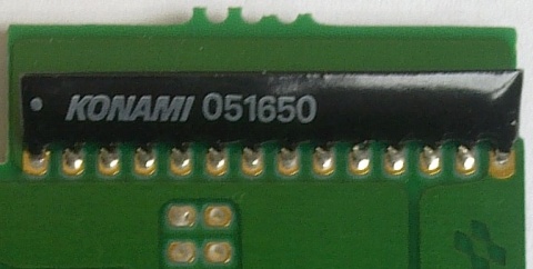
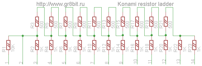
The answer is yes. One of the very well-known multimedia devices for MSX which uses resistor ladder is SCC (Konami Sound Custom Chip). Fig. 1 depicts the rgr8bitesistor ladder, and fig. 2 depicts its internal circuit diagram. The least significant bit (bit 0) of the SCC resulting 11-bit digital waveform representation, is connected to the pins 13. The most significant bit (bit 10) is connected to the pin 3. Pin 2 is an output to the sound mixer, and resistor R1, connected to the ground, serves as a definition of the output impedance of the circuit. Please note that this device, as well as board with SCC chip, does not have decoupling capacitor, as it is expected to be installed at the input of the mixer.
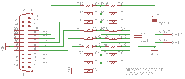
Design of the Covox circuit is more or less unified, with minor differences in the value of resistors, existence of filtering and decoupling capacitors, and output impedance resistor. Look at the circuit shown on the fig. 3. As you may have read in the Wikipedia article about resistor ladders (recommended reading!), it is very important to have one set of resistors to be twice of value to another set. On this diagram, we have 7.5K and 15K resistors, which define the current, and thus amplitude of the voltage at the positive input of the capacitor C1.
In simple words, high level at the output D0 will add specific level of the current (and thus voltage) to the cumulative output waveform, and influence of D0 will be twice less than D1, influence of D1 will be twice less than D2 and so on. D7 will have maximal influence on the level of voltage of the output signal. Keeping ratio between sets of resistors will ensure that these influences are added in linear way, so that, for example, there will be same voltage level delta between having 03h at the data bus (D0 and D1 are high level, others are low), and 04h (D4 is high level, others are low) as in the all other combinations.
Also very important to note that center of the digital waveform element (the number represented by the bit set of D7...D0), or the zero reference point for the whole waveform, should be a value of 080h (bit D7 is high, others low). Therefore positive level of voltage will be represented with numbers 081h and above (up to 0ffh), and negative level of voltage will be represented by numbers 07fh and below (down to 00h). Trying to play 00h-centered waveform will result in corrupt sound. Conversion from 00h-centered to 080h-centered waveform (also called as sample) is performed by signed addition of 080h to the former.
In order to increase the volume of the signal which passes from C1's negative pin to the mixer, you may decrease values of the resistors, still keeping the ratio in their values. However you should be aware that below some minimal value of the 2R resistors, current from high level D outputs will start flowing to the D outputs which are in the low level, and resulting voltage level at the C1 (and thus sound you hear) will become corrupt. This minimal value is dependent on the level of current chip behind D7...D0 lines is able to supply at high level and absorb at low level.
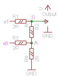
Let's consider simpler version of the device, 2-bit Covox (fig. 4). In this configuration we have four combinations of the input signals [x1x0]: 00, 01, 10 and 11. Figure 5 shows transformed schematic diagrams for every case, with ground at the bottom and supply at the top. We will make several specific assumptions when looking into the details:
Both assumptions represent ideal operation of the circuit. In real life circuit design, as well as properties of input and output devices will add distortions to its operation:
Please note that all voltages are measured against ground (GND) if not specified otherwise.
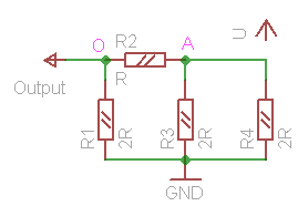
Combination 00: x1=0, x0=0 (fig. 5a). In this case supply voltage does not play any role, and current does not flow anywhere. Output receives ground, or voltage level 0.
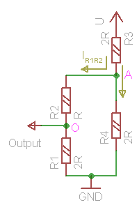
Combination 01: x1=0, x0=1 (fig. 5b). First, we will calculate cumulative current I, flowing through circuit. Cumulative passive resistance of the circuit equals to
| RC = R3 + | (R1 + R2) * R4 | = 2R + | 3R + 2R | = | 16 | R. |
| (R1 + R2) + R4 | 5R | 5 |
Thus current flowing will be
| I = | U | = | 5U | . | |
| 16 | R | 16R | |||
| 5 | |||||
Now we find out the value of voltage between ground and point A:
| UA = U - 2R * | 5U | = U - | 5 | U = | 3 | U. |
| 16R | 8 | 8 |
Now basing on the value of UA, we calculate the value of current flowing through R1 and R2 part of circuit:
| 3 | U | ||||
| IR1R2 = | 8 | = | U | , | |
| 3R | 8R | ||||
and the voltage on the R1 will be
| U0 = | U | * 2R = | 1 | U. |
| 8R | 4 |
In other words, with the input signal combination 01 we have one fourth of the supply voltage on the circuit output.
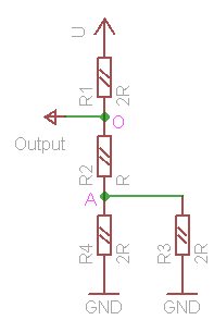
Combination 10: x1=1, x0=0 (fig. 5c). Cumulative passive resistance of the circuit between ground and supply equals to RC = 2R + R + R = 4R, and current flowing through it
| I = | U | . |
| 4R |
Voltage on the output will be equal to
| U0 = | U | * 2R = | 1 | U. |
| 4R | 2 |
In other words, with the input signal combination 10 we have half of the supply voltage on the circuit output.
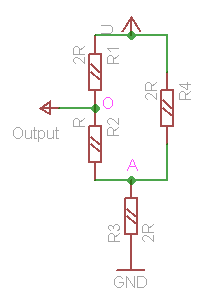
Combination 11: x1=1, x0=1 (fig. 5d). Schematic looks absolutely the same as in combination 01, but connected reversely to the supply and ground. Cumulative current is
| I = | 5U | , |
| 16R |
voltage in point A is
| UA = | 5 | U, |
| 8 |
voltage between supply and point A is
| UUA = U - | 5 | = | 3 | U, |
| 8 | 8 |
current flowing is
| 3 | U | ||||
| IR1R2 = | 8 | = | U | , | |
| 3R | 8R | ||||
and voltage between supply and output is
| UU0 = | 1 | U, |
| 4 |
thus between ground and supply
| U0 = U - | 1 | U = | 3 | U. |
| 4 | 4 |
In other words, with the input signal combination 11 we have three halves of the supply voltage on the circuit output.
Now let's visualize values with the table:
| Combination | Cumulative circuit current | Output voltage |
|---|---|---|
| 00 | 0 | 0 |
| 01 | 5U/16R | U/4 |
| 10 | U/4R | U/2 |
| 11 | 5U/16R | 3U/4 |
What we learn from the mathematical exercise above we made for 2-bit Covox DAC? Here're the points:
In previous chapter we considered relatively simple design, but will our findings hold the true for more complex one? Let's see on the example of the 3-bit DAC, and on the specific combination. Calculations involve more steps as there're more elements involved, and features one very interesting transformation, called Δ-Y transformation (see the link to theory at the end of the article).
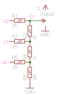
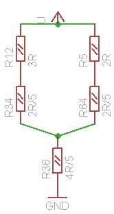
Three-bit DAC (fig. 6) has three digital inputs, and 8 possible input binary states (000b to 111b). We need to identify, which voltage, under the same assumptions as in previous chapter, we will have in the point O when we apply x2=1, x1=0, x0=1 input binary state.
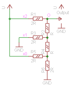
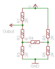
Redrawn diagram under this 101 condition is shown on fig. 7a. You can recognize the device from the fig. 6. However fig. 7b shows the same as 7a, it consolidates same signals applied to the circuit - power and ground wires. In order to identify the voltage in the point O, we need to identify current flowing through resistor R1, but to know it we will have to analyze almost all the circuits flowing between power wires.
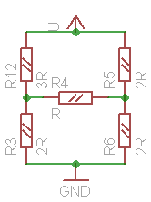
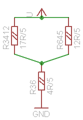
Fig. 7c consolidates R1 and R2 into R12 with value 3R. It is clear, that we now have bridge resistor network, and to proceed we will apply Δ-Y transformation to the resistor triangle R3/R4/R6. After transformation, we get equivalent diagram shown on fig. 7d, with resistors of the following values:
| R34 = | R3 * R4 | = | 2R * R | = | 2R2 | = | 2 | R, |
| R3 + R4 + R6 | 2R + R +2R | 5R | 5 |
| R64 = | R6 * R4 | = | 2 | R, |
| R3 + R4 + R6 | 5 |
| R36 = | R3 * R6 | = | 2R * 2R | = | 4 | R. |
| R3 + R4 + R6 | 2R + R +2R | 5 |
Now we consolidate serial resistors from the left and right arms of the schematic, getting resistors R3412 and R645 (fig. 7e):
| R3412 = 3R + | 2 | R = | 15 | R + | 2 | = | 17 | R; |
| 5 | 5 | 5 | 5 |
| R645 = 2R + | 2 | R = | 12 | R. |
| 5 | 5 |
 (a) |
 (b) |
 (c) |
 (d) |
 (e) |
 (f) |
 (g) |
Figure 7. Analysis of 3-bit Covox DAC, combination 101
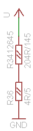
After that we consolidate parallel resistors, and getting fig. 7f:
| R3412645 = | R3412 * R645 | = | 17 | R * | 12 | R | = | 204 | R2 | = | 204R2 | * | 5 | = | 204 | R. |
| 5 | 5 | 25 | ||||||||||||||
| R3412 + R645 | 17 | R + | 12 | R | 29 | R | 25 | 29R | 145 | |||||||
| 5 | 5 | 5 |
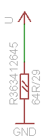
Now again consolidating serial resistors R36 and R3412645, and get single resistance between supply wires (fig. 7g):
| R363412645 = | 204 | R + | 4 | R = | 204 | R + | 116 | R = | 320 | R = | 64 | R. |
| 145 | 5 | 145 | 145 | 145 | 29 |
Therefore, total current flowing through the original circuit will be equal to
| I = | U | = | 29U | . | |
| 64 | R | 64R | |||
| 29 | |||||
So we go back, to original diagram, step by step. Voltage at the R36 equals to
| U36 = | 29U | * | 4 | R = | 29 | R, |
| 64R | 5 | 80 |
and voltage on R3412645 will be
| U3412645 = U - | 29 | U = | 51 | U |
| 80 | 80 |
(fig. 7f, the value we need). This means that resistor R3412 (fig. 7e) is passing current equal to
| I3412 = | 51 | U | = | 51U | * | 5 | = | 3 | U. |
| 80 | |||||||||
| 17 | R | 80 | 17 | 16 | |||||
| 5 |
The same current is flowing through R34 and R12 (fig. 7d and 7c), and R1 and R2 (fig. 7b). Therefore voltage on the resistor R1 equals to
| U1 = | 3 | U * 2R = | 3 | R, |
| 16 | 8 |
and voltage between output and ground will be
| UO = U - U1 = | 5 | U. |
| 8 |
So what we learnt from this exercise? It confirmed our findings with 3-bit DAC that voltage scale is divided into n2 ranges (1/8), and voltage value is at lower boundary of the range for every combination: 101 binary is 5 decimal, resulting 5U/8 potential of output relative to ground.
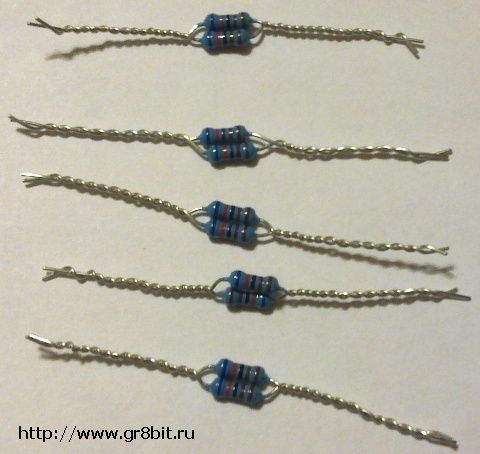
We decided to take 2R value of 6.2kOhm, and thus having R value to equal to 3.1kOhm. To get best quality possible we chosen 1% tolerance resistors, and as 3.1kOhm resistors are not easily available on the market, construct this value by connection two 6.2kOhm resistors in parallel. In general case, when you connect two, three or more resistors in parallel, resulting resistance is calculated by the following formula:
| R = | R1 * R2 * … * Rn | , |
| R1 + R2 + … + Rn |
and in our particular case with two resistors of same value it will be
| R = | 6.2 * 6.2 | = | 38.44 | = 3.1 (kOhm). |
| 6.2 + 6.2 | 12.4 |
Therefore we will need 9+8*2=25 resistors of the same 6.2kOhm nominal.
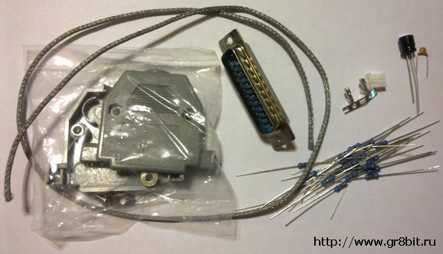
In addition to resistor, we will need one ceramic filtering capacitor (0.01µF), one electrolytic capacitor (100µF/16 volts), and 25-pin two row male D-SUB connector with casing as large a s possible to hold the electronics we are to build into it. We will also need a piece of shielded wire, and connector at another end of this wire (fig. 8).
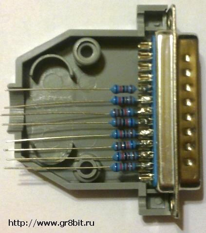 (a) Cut one side of the pins of 8 resistors, leaving about 5 mm to solder to the connector's pins |
 (b) bend R1's pin and solder it to the ground pin of connector (in our case, to pin 25) | |
 (c) cut 8 resistors' other pins, and bend small hooks at their ends carefully. Solder R1 to the R3 |
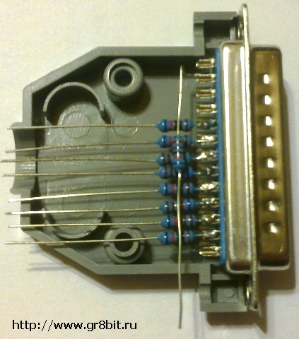
 (d) connect 8 pairs of the resistors to form a circuit of twice less nominal | |
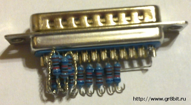 (e) Bend their pins as shown above, and start soldering to the hooks of the resistors, alternating the sides (i.e. R3/R5 from one side of the connector, R5/R7 from another side) |
||
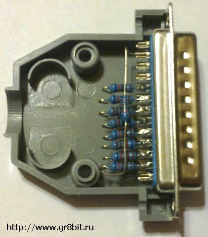
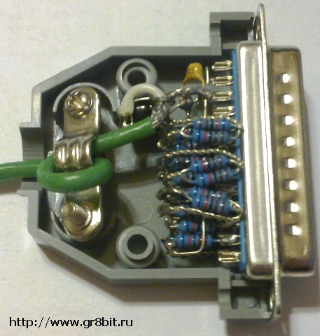 (f) at the end solder C1, C2, solder shielded wire (which was previously prepared as described in your GR8BOOK part II subchapter 3.4) |
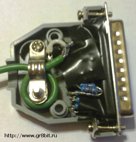 (g) put electric tape so that resistors at the connector sides do not short-circuit with its body, and wire's shield do not short-circuit with any junction | |
Figure 9. Assembling the device
You have several options how to connect components to each other - use breadboard, or use point-to-point connection. Given the number of components, their size and relatively small size of the connector casing, we have chosen to use point-to-point connection. In this style of build, the most important task, along to ensuring that all components are connected reliably, we should ensure that, as they are only fixed with their pins, they do not short-circuit with other components. Covox does not have components which excessively heat, and we just use electrical tape to isolate component pins and junctions.
Here's the list of steps we have taken:
Well, you can test it in your PC's parallel port too, but let's focus on which tools are available to test in on GR8BIT.
We provide program called COVOX which streams media file in the format of 11025Hz, 8 bit sample and single channel, to the parallel port of your GR8BIT. It also visualizes the waveform on the screen. This program runs properly on the accelerated GR8BIT because it heavily uses I/O access (to printer port 091h and video ports 099h and 098h), and GR8BIT is steadily running at the CLKLO speed (please refer to KB0009: Accelerating your GR8BIT).
The command line format is
where "filename" is a name of the media file in WAV format, in 8.3 notation. This file can be of any size.
Program identifies the size of the RAM available, and uses all its pages from #4 up pre-fetching the data to play. As buffer had been played, playback stops until new chunk of the wave data is loaded into the RAM. Due to the speed constraints it is not possible to perform playback and mass storage I/O (waveform data read) simultaneously. COVOX.COM works in DOS1 mode only, because it bypasses DOS2 memory allocation routines. It is rather than demonstration and a piece for your further development, than fully functional application. It can be downloaded in the Downloads section of the website.
COVOX.COM works fine in the emulators, if you insert "SiMPL/Covox DAC" into parallel port in BlueMSX, "simpl" device into the printer port in OpenMSX (fig. 10).
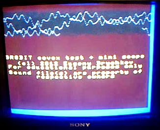 (a) GR8BIT |
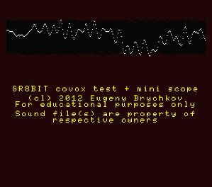 (b) BlueMSX |
Figure 10. Running COVOX.COM in the real machine (a) and emulator (b)
End of KB0010 "Adding a multimedia capability: a Covox device".
KB article release notes: KB0010 was initially released on October 19, 2012. It was amended:
| © 2011-2024 Eugeny Brychkov | http://www.gr8bit.ru | Status: Released |
 |
|||||

|

|
GR8BIT™, GR8BOOK™, GR8BUS™, GR8BOX™, GR8STORM™ and GR8NET™ are trademarks
copyright © 2010-2024 Eugeny Brychkov.
Please refer to: copyright statement,
privacy policy.