| Apr 24, 2018 | Severity: Information | Eugeny Brychkov (RU) |
At the beginning of the development of the GR8NET adapter I was supplying ByteBlaster-II device, which I developed to update GR8NET's FPGA. I still use it because I have PC having parallel port with Quartus II installed, but I was told that parallel port is a rarity these days, and supplying ByteBlaster device has no sense because it can not be used.
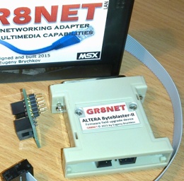
In order to update GR8NET's FPGA configuration chip people had to buy or rent USB blaster device. The original Altera device is relatively expensive, thus most of you decided to acquire the clone, which costs around $10.
These days, while I have built update of the EPCS16 chip, installed in GR8NET, through MSX machine, sometimes external programming device is required. In general, it is recommended to have anyway emergency purposes anyway.
Although I had several reports that people are having difficulties using their USB blasters to update GR8NET, most of the cases the issue exhibits when Quartus starts accessing the chip reading its silicon ID, and reporting that it Can't recognize silicon ID for device. The main troubleshooting issue here is that Quartus does not give any further diagnostic information, and such situations is simply impossible to troubleshoot to see what is actually wrong, and which device is involved and to be replaced – would it a USB blaster, ribbon cable, connector adapter, USB cable, Quartus application or operating system, or GR8NET.
I have got a thought that it would be great to have some solution allowing having deep troubleshooting information if something goes wrong, not relying on third party intermediary hardware and software. My hand-made ByteBlasters are great, but they use parallel port...
And then I have got an idea – MSX machine is having needed ports! It has parallel port, and joystick ports, why not using machine to configure itself?
The solution must be easy to assemble, use components easily available on the market. It must not be universal, it just must allow you to perform required operation, and that's all.
I decided to use joystick ports for connection because they use standard DB9 male connector, in contrast to Centronics 14 pin connector for MSX parallel port which is very specific.
Next, I decided to simplify ByteBlaster circuit in order to have least soldering exercise, and minimize number of components.
The device utilizes only one chip, 74HC367N, several resistors, capacitors and two connectors. Important: chip must be HC-type.
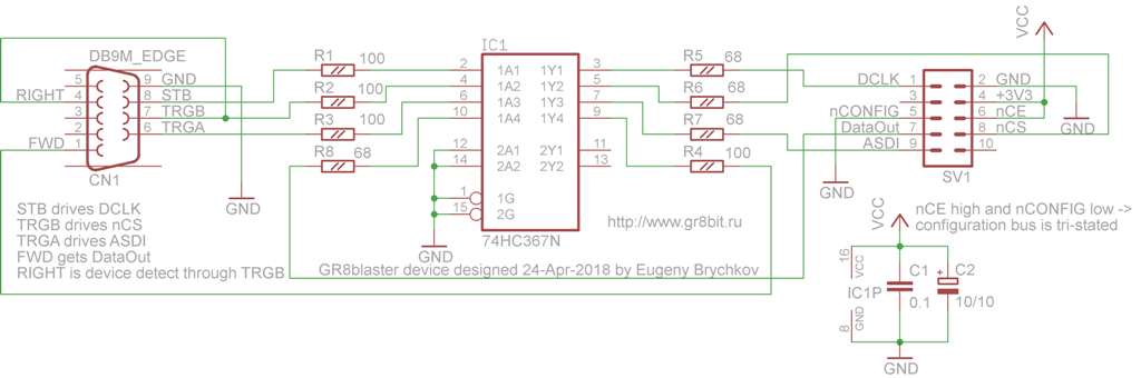
Only three signals required to control EPCS16 chip are fed from the machine – nCS, DCLK and ASDI, and only one wire is fed from EPCS16 to the machine – DataOut. When connector SV1 is connected to the GR8NET, it hardwires signals nCONFIG to ground and nCE to high level, causing FPGA chip to deactivate and release EPCS16 configuration device for access through GR8blatser device.
It is important that chip is powered from the GR8NET, and there're 100 Ohm resistors between 5V signal pins and the chip to limit the current. At no circumstance 5V pins from MSX machine may be connected directly to wires of the SV1 connector.
The detection of the GR8blaster device is performed through TRGB-RIGHT connection. Good thing in this design is that everything is referenced to the common ground of the same machine.
GR8NET's FPGA will not configure until SV1 connector is disconnected from the cable.
After finishing assembly you can send pictures of your device's board to info@gr8bit.ru for review.
While task looks like an easy one, it requires a degree of persistence, patience and thoroughness. There should be no hurry, and careful checking must be done after assembly.
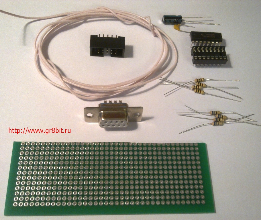
You will need the following parts:
When choosing layout of the components on the board:
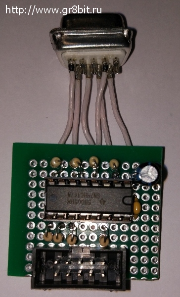 GR8blaster device, component side |
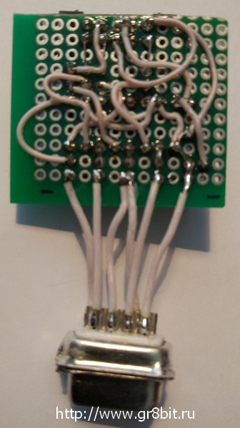 GR8blaster device, solder/wiring side |
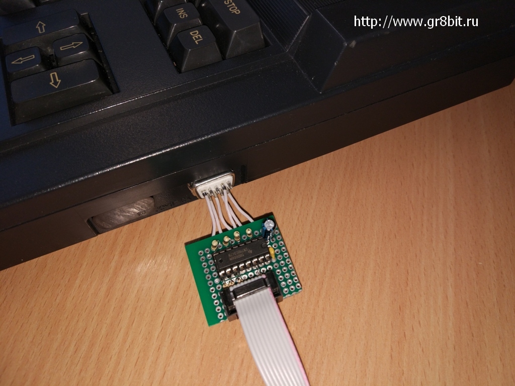 GR8blaster device connected to the Yamaha MSX joystick port |
|
After soldering, take a magnifier, and carefully check whole board you just made against missing connections and shortages. Remember – connecting 5V wires from MSX directly to the GR8NET's programming interface (or even through small resistor like you used – 100 Ohm or 68 Ohm) may cause damage to the GR8NET and particularly FPGA, thus if you are not sure there's no shortage, it would be a good idea to rework so that no shortage is clearly seen.
If you used thick enough wires to connect DB9 connector, you will be able to remove connector from MSX's joystick port by pulling the wires. The point here is that these wires must be soldered to the pads, and must be straight, without bends.
One more issue to be aware of – it may happen that DB9 connector's pin holes are too narrow for MSX joystick port connector male pins; I used relatively thick awl to carefully widen the holes, until connector inserts into MSX port with some pressure, but without excessive force.
Software is written in BASIC, and can be loaded from any other MSX storage device, even from the network (through _NETBROWSE) if you have second GR8NET installed in the system. You can not use GR8NET connected to GR8blaster as source of code or data for simple reason – its FPGA is down, and device does not function at all during the operations.
The location of the application is http://www.gr8bit.ru/software/basic/utilities/gr8blast.asc. You can copy it freely to any needed storage, together with the data files you will need to flash the EPCS16 chip.
As soon as program starts, it deploys its assembly routines, checks for MSX AY8910 ports configuration, and reads silicon ID of the device connected with the programming ribbon cable. For EPCS16 contained in GR8NET silicon ID will be &H14. If all these steps are successful, main menu is displayed.
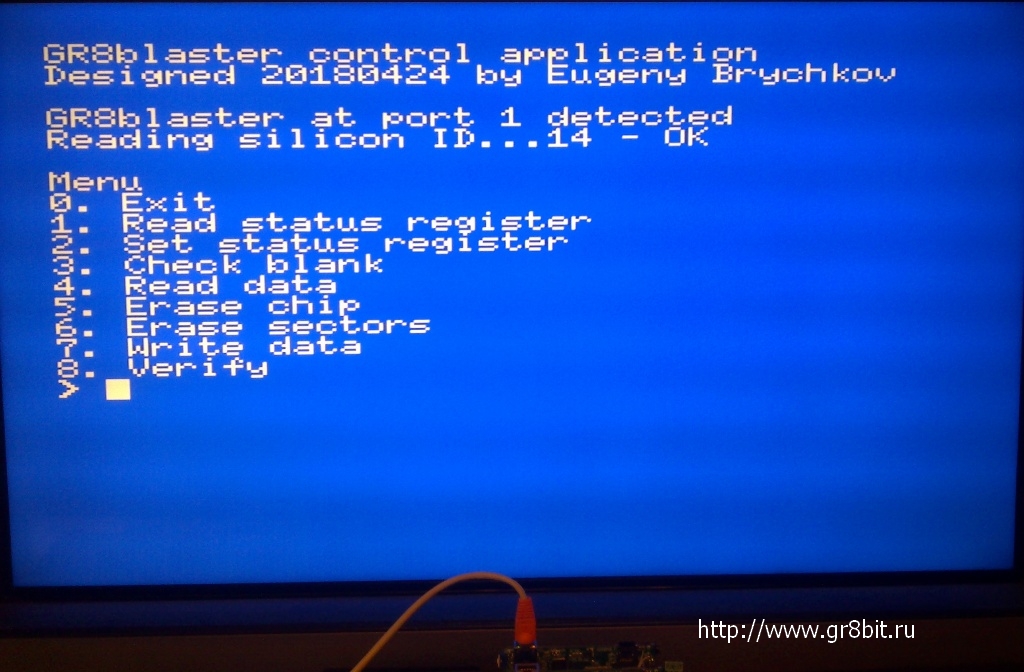
Most of the items are intuitive enough, however let's consider each one to ensure you will use the ones you require from the first try properly.
| Action | Description |
|---|---|
| Exit | You will exit to the BASIC |
| Read status register | There will be a byte read from the EPCS16 called status byte, which will indicate sector protection status. Normally the value of status byte is 0 |
| Set status register | This is advanced selection, and you can supply the specific bits protecting your EPSC16 from writing. Should not be used unless instructed |
| Check blank | This selection will just read whole EPCS16 chip seeing if all its bits are 1s. If there will be 0s, it will report address of occurrence. Operation may take quite a time without displaying anything and CAPS lock not functioning |
| Read data | Reads the data into the file. Displays dots each 8K block written to the storage device |
| Erase chip | Erases whole chip at once. Requires you to confirm the action pressing uppercase Y. After this operation chip is expected to be completely blank, and GR8NET will become "bricked", until you write appropriate configuration data into specific sectors |
| Erase sectors | Allows you to select which sectors you want to erase. EPCS16 has 32 sectors of 64KB each (thus in total 2MB of space) |
| Write data | Reads data from the file and writes it into the selected sectors |
| Verify | Compares data in specific sectors in the EPCS16 chip with the contents of the file |
Operations which involve data exchange or verification will require your system to have compatible MSX storage installed in the system, with required files or space for new files in it. Source images must have size of multiple of 8192.
You can not use files called gr8net-fpga-reg.bin or gr8net-fpga-mp3.bin for flashing the image using GR8blaster application, you must use special recovery image called gr8fpgar.raw without any headers which contains raw data only. This file is located in firmware directory on the server.
Use case example: GR8NET became non-operational due to corruption of its factory image. The only way is to use blaster device. In this case you can use GR8blatser device without need in any other PC or software line Quartus. Thus you connect GR8blaster to joystick port 1, and to GR8NET, installing GR8NET into machine together with floppy drive, MFR or second GR8NET (in mapper mode 8). You copy gr8blast.asc file and gr8fpgar.raw to the storage device, and run gr8blast BASIC program from there. When it gets to menu, you check status register to be 0, then (optionally) read first 8 sectors of EPCS device for future analysis, and then erase the chip, then blank check it, and write gr8fpgar file contents to it. After performing these actions you power off the machine, disconnect update cable adapter from GR8NET, and it should start working properly.
End of KB0018 "GR8blaster device for MSX".
| © 2011-2024 Eugeny Brychkov | http://www.gr8bit.ru | Status: Released |
 |
|||||

|

|
GR8BIT™, GR8BOOK™, GR8BUS™, GR8BOX™, GR8STORM™ and GR8NET™ are trademarks
copyright © 2010-2024 Eugeny Brychkov.
Please refer to: copyright statement,
privacy policy.