| Nov 08, 2013 | Severity: Information | Eugeny Brychkov (RU) |
Background: In the default configuration GR8BIT has two video outputs:
It is a great pity that not every TV or monitor feature RGB input which support 15kHz dot clock frequency, and sometimes it is really hard to get full fun of color picture. Here we offer easy solution, and we hope you will get fun from building the small board which will allow you to get color picture through CVBS wire and S-video interfaces.
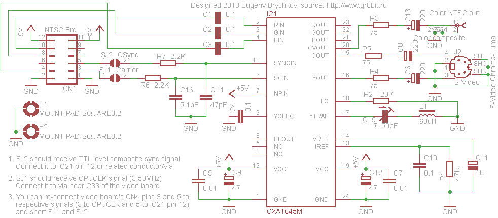
Solution: Our recommendation is to use single NTSC/PAL encoder chip; we selected CXA1645, which is available in both DIP (P) and SOP (M) packages. The schematic shown on fig. 1 uses encoder chip in the NTSC mode, which is default for GR8BIT (60Hz frame rate). To have PAL TV connected to the GR8BIT, you will need to put CXA1645's pin 7 to ground instead of +5v, attach 4.43MHz clock source to the R6's left pin, and put VDP into the PAL mode by setting register #9 bit *NT to 1 typing from BASIC prompt "VDP(10)=VDP(10)OR2".
4.43Mhz clock source is missing in the GR8BIT, thus it will be externally brought component (for example, quartz generator). Opportunity to choose between 50/60Hz modes would be the next improvement item for the GR8BIT language pack.
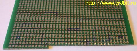
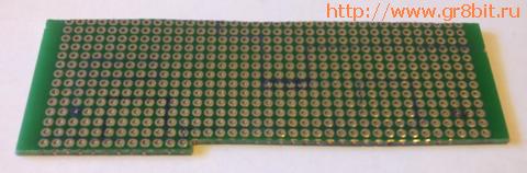
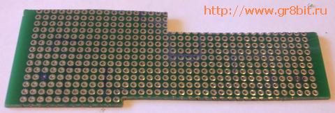
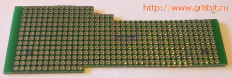
Figure 2 shows the PCB. You may not need to use these images if you decide to build circuit in point-to-point wiring manner (fig. 3). What you should remember that this additional board is installed above the GR8BIT Video board, and you should have components which you solder on this board's inner surface (which goes face-to-face to Video board) to fit empty space on the Video board.
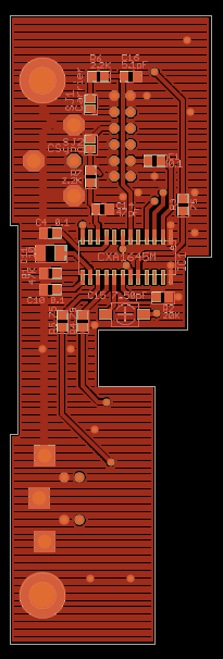 | 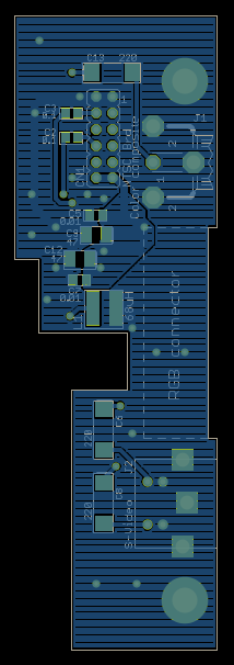 | |
| (a) outer surface | (b) inner surface | |
| Figure 2. PCB layout | ||
Assembly instruction: here is step-by-step point-to-point wiring method assembly instruction. While designing your and assembling, remember that components on the board should fit into the space empty from component bodies mounted on the Video board. Also, height of the whole assembly should not be higher than height of one standard ISA card unit (i.e. width of the bracket), otherwise you will not be able to install other cards to the right of video board.
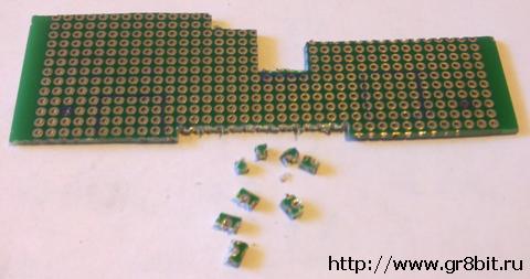
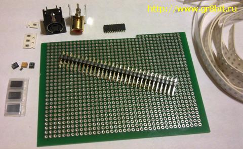 (a) collect all needed components |
 (b) mark the dimensions of the board and positions of the holes with marker | |
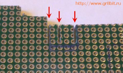
 (c) cut long edge |
 (d) cut the next | |
 (e) cut another small one |
 (f) scarify inner dimensions | |
 (g) and break off the pieces out |
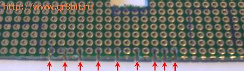 (h) same with another inner dimension | |
 (i) and break off |
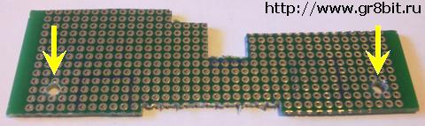 (j) drill the mounting holes | |
 (k) use file to smooth dimensions |
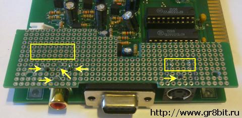 (l) find out exact location of the CN1. Locations of connectors and drill mounting holes for them | |
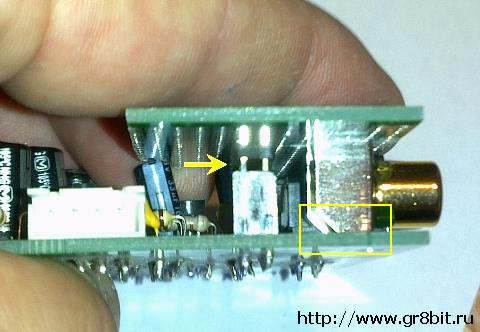 (m) check the height: CN1 should firmly fit into video board's CN4. If not - file dimensions of the top of connectors down |
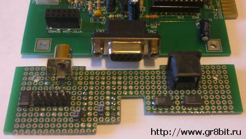
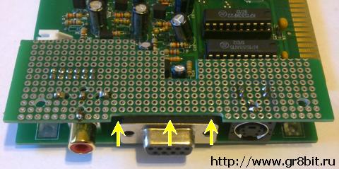 (n) then solder connectors. Board at the points of arrows should be almost adjoin (lie on) the video board's DB-9 connector's body | |
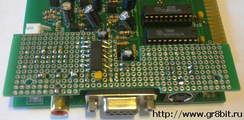 (o) solder components onto outer surface |
 (p) solder components onto the inner surface | |
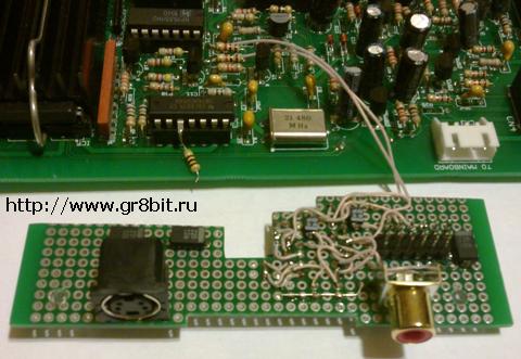 (q) wire from the inner side |
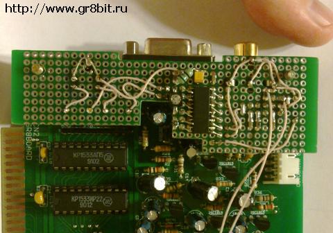 (r) wire from the outer side | |
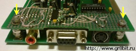 (s) put boards together |
 (t) and you will get the color | |
| Figure 3. Process of making the board | ||
End of KB0014 "Composite and Y/C Video Board".
| © 2011-2024 Eugeny Brychkov | http://www.gr8bit.ru | Status: Released |
 |
|||||

|

|
GR8BIT™, GR8BOOK™, GR8BUS™, GR8BOX™, GR8STORM™ and GR8NET™ are trademarks
copyright © 2010-2024 Eugeny Brychkov.
Please refer to: copyright statement,
privacy policy.